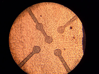
Five pin package - piece of cake, right? But, just to add to the fun, the package I picked was CSBGA with balls about 250μm apart!
From the packaging specification, it can be seen that the balls are 150 μm diameter and spaced in a 2x2 grid 570μm x 520μm with one more in the center. This is a little smaller than my laser-printer contact lithography process can comfortably resolve. What to do?
Conveniently I have a metallurgical microscope that I've managed to coax into service as a projection lithography system. The field of view is, however, far too small to do an entire PCB.
After a little thinking I decided to try a multiple-exposure technique. The first step was to design a board layout in ExpressPCB (my preferred CAD tool is kicad but Express is a little easier for super simple layouts) with a 4-pin SIL header going to a rectangle of copper a little bigger than the CSP footprint. I also made a second mask containing the BGA footprint and tracks going out to four large pads, and printed it at 4x actual size. The center ball is WP# so I tied it to Vdd rather than breaking out to a separate pin.
 |
| Mask design |
I then printed a mask on my printer, exposed onto precoated PCB, developed (1% w/v NaOH in distilled water), and etched (6 parts 3% H2O2 : 1 part 32% HCl at low heat) as with my standard PCB process.
The next step was to strip the existing photoresist since it had been exposed to light during the etch process. A few drops of acetone did the trick nicely.
I then spin-coated the board with fresh photoresist, using my standard mixture (Shipley SP24 photoresist diluted 50% v/v with acetone for a thinner layer), soft baked on a hot plate, and exposed the BGA mask onto the copper rectangle. After developing, this was the result:
 | ||
| Second photomask on top of etched metal1 |
 |
| Closer view showing edge quality |
Since the thin photoresist I use is harder to see on copper than the thick stuff the board came coated with, I tossed it in the etchant for a couple of seconds to make it more obvious what was being masked.
 |
| After a couple seconds in the etch bath |
The copper pad was also a bit larger than it needed to be and exceeded the FOV of the lithography system (note the unwanted photoresist shorting the pads together). I gently scraped this away with a #11 scalpel blade under 30x magnification and briefly etched to confirm good separation.
 |
| Surgery time! |
 |
| After etching, no shorts |
I then etched for a couple of minutes and removed the board to see how it was doing.
 |
| Almost done etching |
 |
| Overetched. (photoresist stripped before taking this pic) |
In either case, had the traces been a little larger (perhaps 75 μm) or the copper a little thinner it would have worked beautifully. The lithography itself was flawless and even though the board was not usable it appears the technique is feasible. Given a mask respin this same board could be fabricated with little difficulty.