 |
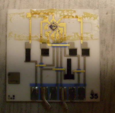
| Sensor board |
The brownish reside on the top of the board is adhesive residue from the encapsulation over the sensor die.
 |
| Sensor die |
The sensor die is approximately 1600μm along each side and appears to be made from a <100> oriented silicon wafer. Two metal layers are visible - one of a resistive material (most likely polysilicon) and one of gold (used for bond pads). For the sake of discussion I will define the upper center pin to be pin 1.
The die consists of six resistors and is entirely passive, with no transistors whatsoever.
The active sensing element consists of two membranes made out of what appears to be silicon nitride. The membranes are suspended over a cavity defined by an anisotropic wet etch using a KOH or related chemistry.
There are a total of three resistors between the membranes, whose values presumably change as the membrane is stressed. Pins 1 and 2, as well as 3 and 4, are connected to thin zigzag resistors on the left and right membranes respectively. Pins 7 and 8 connect to another resistor which starts on the lower left of the upper membrane, loops around at the far side, and goes back to the lower left on the lower membrane.
In addition, there are three resistors on the silicon substrate - betweens pins 8 and 9, 7 and 6, and 6 and 5. While they are all bonded out to pads and would be easy to measure, I have not yet attempted to get resistance readings.
The resistor between pins 5 and 6 has very unusual geometry and is not the typical zigzag I would expect. There is no obvious reason for this pattern.
Very interesting reading.. I also recently looked under the skirt of a pressure sensor too.. See http://www.varesano.net/blog/fabio/inside-ms5611-high-resolution-barometer
ReplyDeleteUnfortunately, I destroyed it by mistake while handlying so I couldn't make 400x magnified pictures..
This is flow sensor. Membrane is actualy thermal insulation geometry. There is wire that is heat generator and resistor that change resistans based on temperature which is different based on air flow (direction and intensity).
ReplyDeleteYeah, I figured that out when I found a datasheet for the part (see my next post in the series).
ReplyDeleteIn parallel, the business roles will expand to include market research and product definition. In a start-up, the day-to-day finance and operations roles (accounting, legal, human resources, facility, and so on) must also be added to keep the company operational. thought leadership
ReplyDeleteThe term “package ,” when used by MEMS or semiconductor engineers, refers to a structure that encloses a silicon chip. The MEMS package has several important functions. The package is the mechanical and electrical interface between the MEMS chip and the greater system. It is also the interface between the MEMS chip and the sensed/actuated phenomenon. Finally, the package protects the MEMS from the operating environment. what is thought leadership marketing
ReplyDelete